
B44066T****E402 · Version 4 · September 2013
What the TSM-LC is
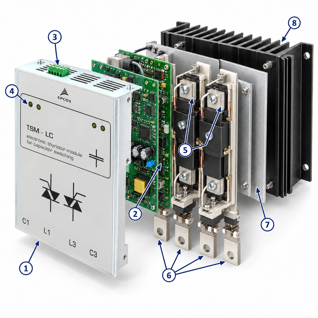
The TSM-LC series for dynamic PFC are fast, electronically controlled, self-observing thyristor switches for capacitive loads. They switch PFC capacitors within a few milliseconds, as often and as long as required, and replace the contactor in a dynamic (“real time”) compensation step. Triggering can come from a dynamic power factor controller, a PLC, or directly from the installation with an adequate control signal.
Applications — fast, highly fluctuating loads
- Pressing
- Welding machines
- Elevators
- Cranes
- Wind turbines
- Any fast changing load
Features
- Component for the design of dynamic PFC systems in 380 V and 400 V grids (50/60 Hz)
- Automatically adapted by microprocessor to detuned and conventional capacitor branches (up to 14 %) — optimised switching behaviour
- Available for capacitive loads from 10 to 200 kvar
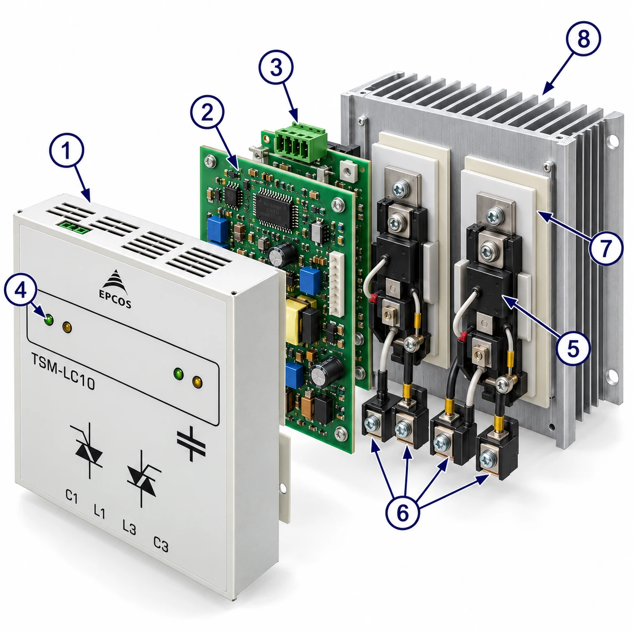
- Monitoring of voltage, phase sequence and temperature; status LEDs
- Switching without time lag; no system perturbation (no transients); no noise during switching
- TSM-LC100 and TSM-LC200: auxiliary voltage 230 V AC needed for the fan
- Maintenance-free, long operational life, compact design ready for connection
Installation and connection
- 1Mount the module directly on a mounting plate, vertical, with at least 100 mm free space above and below and 50 mm on the left and right.
- 2The main terminals are bus bars or terminal clamps: connect them directly to the branch fuse and to the capacitor (pictures 1 – 3).
- 3Use superfast electronic fuses as branch fuses to protect the semiconductor — this is mandatory, and the basics of dimensioning must be obeyed.
- 4Feed the trigger signal (10 – 24 V DC from a dynamic PF controller or an adequate control system) into the input-signal terminal. Triggering acts without delay.
- 5If a larger stage output is needed, several modules can be cascaded.
Discharge resistors and current-limitation reactors
Fast discharge resistors EW-22
If a fast re-switching time of the capacitors is required, the fast discharge resistors EW-22 (ordering code B44066T0022E400) have to be used — at least one per step for all TSM-LC types.
| Module | EW-22 needed |
|---|---|
| TSM-LC-I (single-phase) | standard resistor sufficient |
| TSM-LC10, TSM-LC25, TSM-LC50 | 1 |
| TSM-LC100 | 1 – 2 in parallel |
| TSM-LC200 | 2 – 4 in parallel |
PFC systems without detuning reactors
Current limitation reactors of the BD series have to be used, two units per step. The TSM-LC200 is only suitable for detuned systems, so it needs no current limitation reactor.
| Module | BD reactors | Ordering code |
|---|---|---|
| TSM-LC-I | 1 × BD-100 | B44066T0100E400 |
| TSM-LC10 / 25 / 50 | 2 × BD-100 | B44066T0100E400 |
| TSM-LC100 | 2 × BD-200 | B44066T0200E400 |
| TSM-LC200 | none (detuned systems only) | — |
Putting into operation
After switching on the voltage (engaging the branch fuse) the module is ready for operation. When the voltage is switched on for the first time, the internal processor optimises the switching behaviour to the connected steps (with or without reactors) and stores these parameters internally, giving optimised switching times later.
Status LEDs, per phase
- standby
- module on
- under-voltage
- phase missing
- over-temperaturevaries with the type of switch
Technical data
| Net voltage | 380 … 400 V (50/60 Hz); TSM-LC-I (single-phase): 230 … 525 V |
|---|---|
| Auxiliary supply | TSM-LC-I: 24 V DC; TSM-LC100 and TSM-LC200: 230 V AC |
| Max. voltage allowed | conventional PFC (without reactors): 440 V · detuning 7 %: max. 440 V (no upward tolerance) · detuning 14 %: 400 V |
| Max. current | depends on cooling and location of the system — in doubt, contact the regional sales representative |
| Activation | 10 … 24 V DC (approx. 20 mA) via terminal clamp, internally galvanically uncoupled |
| Switching time | approx. 5 ms |
| Re-switching time | depends on the degree of detuning and the capacitor’s discharge resistor |
| Display | 2 LEDs per phase: operation / error plus triggering signal |
| Monitoring | permanent monitoring of net voltage, phase, temperature and operation status |
| Main circuit | direct connection, 4-pole via bus bar / terminal clamps (TSM-LC-I: 2-pole, single-phase switching) |
| Power dissipation | Pv (W) = 2.0 × I (A); at 400 V / 50 kvar approx. 150 W |
| Mounting position | vertical; min. 100 mm upwards and downwards, min. 50 mm right and left; direct mounting on the plate |
| Operating ambient temperature | –10 °C … 55 °C at nominal load |
Fuses — 3 × electronic “superfast”
| Module | Fuse |
|---|---|
| TSM-LC-I | 63 A (NH00, AC 690 V) |
| 10 kvar | 35 A (NH00, AC 690 V) |
| 25 kvar | 63 A (NH00, AC 690 V) |
| 50 kvar | 125 A (NH00, AC 690 V) |
| 100 kvar | 250 A (NH1, AC 690 V) |
| 200 kvar | 450 A (NH2, AC 690 V) |
Dimensions and weight
| Module | W × H × D (mm) | Weight |
|---|---|---|
| TSM-LC-I | 70 × 200 × 150 | 1.5 kg |
| TSM-LC10 | 163 × 152 × 75 | 1.75 kg |
| TSM-LC25 / 50 | 157 × 200 × 180 | 4.8 kg |
| TSM-LC100 | 157 × 240 × 195 | 5.5 kg |
| TSM-LC200 | 250 × 480 × 160 | 11.5 kg |
Connecting diagram
Safety, maintenance and notes
General
- The TSM-LC thyristor modules may only be used according to their intended utilisation and only in combination with appropriate safety devices (e.g. superfast fuses).
- Install them so that no uncontrolled high currents and voltages can occur in case of faults; in critical networks install surge arresters or other protection externally.
- Protect the devices against humidity and dust and assure sufficient ventilation.
- Connect them to the grid only if any possible harm or danger to human beings or the PFC system is eliminated.
Maintenance, repair
Deactivate the TSM switch and release the main circuit breaker; make sure the TSM cannot be switched on during maintenance and check that there is no voltage at all. Maintenance is for specially skilled personnel only; repairs only by the manufacturer of the TSM-LC module. Failure to follow the cautions may result, worst case, in premature failures or physical injury.
Important notes (EPCOS)
- Statements about the suitability of products for certain applications are based on typical requirements and are not binding; the customer must check whether a product is suitable for the particular application.
- A malfunction or failure of electronic components before the end of their usual service life cannot be completely ruled out; applications with a very high level of operational safety need protective circuitry or redundancy.
- Warnings, cautions and product-specific notes must be observed; some products may contain substances subject to restrictions (see the Material Data Sheets); products and specifications may change — check before ordering.
- Orders are subject to the “General Terms of Delivery for Products and Services in the Electrical Industry” (ZVEI) unless agreed otherwise. EPCOS, MKK, PhaseCap, PhiCap and the other names listed are registered trademarks.
این صفحه بازنویسی سند اصلی است؛ در صورت اختلاف، فایل اصلی سازنده معتبر است. برای پرسشهای فنی تماس با ما