EPCOS AG · Power Quality Solutions · Version 6.0 E · March 2012
General, types and accessories
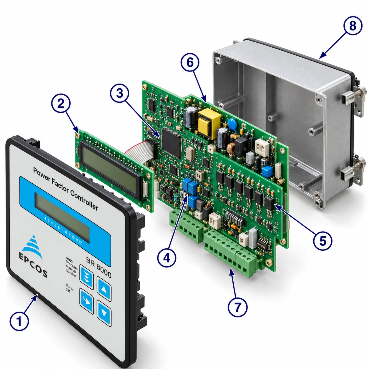
The dynamic power factor controller BR6000-T is the consequent development of the BR6000 series, now in V6. It has been designed to control thyristor modules for dynamic switching of power capacitors (for example TSM-LC). A very fast processor gives extremely short switching cycles; in addition to a switching time under 20 ms, the intelligent control principle tunes the power factor by simultaneous switching of several steps. Operation is menu-guided in plain text with symbols in 10 local languages.
Main features
- Six or 12 switching outputs (depending on the type)
- Measuring voltage 30 … 525 V (L-N) or (L-L); supply voltage 110 … 230 V AC
- 20 pre-programmed control series with self-optimised intelligent control response, plus a control-series editor
- Complete menu-guided operation and display (10 languages); illuminated graphic display 2 × 16 characters
- Four-quadrant operation; display of V, I, F, Q, P, S …; display and monitoring of temperature
- Monitoring of capacitor power values with the accessory MMI6000; storage of maximum line parameters
- Manual / automatic operation; programming of fixed stages and skipping of individual outputs
- No-voltage turn-off; error detection for various states with interference-message output
- Complete 2nd parameter set, programmable / switchable; switchboard-integrated housing 144 × 144 × 55 mm
Type series
| Type | Outputs | Extras |
|---|---|---|
| BR6000-T6 | 6 transistor outputs | 1 alarm relay |
| BR6000-T12 | 12 transistor outputs | 1 alarm relay |
| BR6000-T12/S | 12 transistor outputs | additional message relay; external input (e.g. for the 2nd parameter set); RS485 interface, controller coupling possible |
Accessories
| Accessory | Purpose |
|---|---|
| MMI6000 — MultiMeasuringInterface | measurement of the inherent current of the capacitor bank |
| Interface converter RS485 → USB | PC connection |
| Interface converter RS485 → RS232 | older PCs |
Installation and connection
The BR6000 is built into the front panel of a PFC cabinet: it needs a switchboard section of 138 × 138 mm (DIN 43700 / IEC 61554), is inserted from the front and fixed with the appended clamps. Only qualified technicians may insert it, observing the specified safety regulations. Before connection, check that no current flows through the leads and short-circuit the current converter. Make sure measuring voltage and current are in the correct phase position; wire the measuring-current circuit with 2.5 mm² copper leads.
Current measurement
The load current must flow through the current converter; the outputs of the compensation network are installed behind the converter in the direction of current flow. With sum-current converters the overall conversion ratio is entered — example: converter 1 = 1000/5 A, converter 2 = 1000/5 A, sum converter 5 A + 5 A / 5 A → ratio 2000/5 A.
Programming of phase correction
Adjustment of the phase correction between voltage and current is done in expert mode 1. Example: measuring current L1, measuring voltage L3 – L2 → phase U/I = 90°.
| Meas. current | Meas. voltage | Phase angle |
|---|---|---|
| L1 | L1 – N | 0° |
| L1 | L1 – L2 | 30° |
| L1 (k↔l) | L2 – N | 60° |
| L1 | L3 – L2 | 90° |
| L1 | L3 – N | 120° |
| L1 | L3 – L1 | 150° |
| L1 (k↔l) | L1 – N | 180° |
| L1 (k↔l) | L1 – L2 | 210° |
| L1 | L2 – N | 240° |
| L1 | L2 – L3 | 270° |
| L1 (k↔l) | L3 – N | 300° |
| L1 (k↔l) | L3 – L1 | 330° |
Alarm output, error messages and operating modes
The alarm contact is closed in normal operation and opens in the event of a fault; the fault is shown on the display in plain text, alternating with the standard display. Messages can be individually suppressed in expert mode 2.
- UNDER-COMPENSATED
- OVER-COMPENSATED
- OVERCURRENT
- MEASURING VOLTAGE ?
- OVERTEMPERATURE
- OVERVOLTAGE
- UNDERVOLTAGE
- HARMONICS
Operating modes
When the operating voltage is switched on, the BR6000 briefly shows its designation and software version and then goes to automatic operation. The active cos φ is always in the upper line; the connected capacitors are shown as symbols in the lower line. A closed arrow shows the control direction (connecting-in / connecting-out), an open arrow that the blocking (discharge) time is running, a double arrow the fast switching of several branches.
Automatic operation and the transistor outputs
In automatic operation capacitor stages are connected or disconnected to reach the target power factor whenever the required reactive power exceeds the smallest stage. Pressing ENTER repeatedly shows the network parameters; after 60 s without a key the display returns to the operating status.
| ENTER | Display |
|---|---|
| 1 | LINE VOLTAGE in V |
| 2 | APPARENT CURRENT in A / % |
| 3 | REACTIVE POWER in kvar / % |
| 4 | ACTIVE POWER in kW / % |
| 5 | APPARENT POWER in kVA / % |
| 6 | DIFF. kvar TO TARGET COS |
| 7 | FREQUENCY in Hz |
| 8 | TEMPERATURE in °C / °F |
| 9 | HARMONICS (3rd – 19th) V/%, I/% |
| 10 | THD-V; THD-I in % |
| 11 | Software version, then back to 1 |
Programming menu
Press the “Operating mode” key once to enter programming. The upper line shows the parameter, the lower one the set value; ▲ ▼ change it and ENTER stores it and moves on. Press “Operating mode” to quit at any step.
| No. | Parameter | Range | Notes |
|---|---|---|---|
| 0 | LANGUAGE | G / E / ES / RU / NL / CZ / PL / F / PT / TR | German, English, Spanish, French, Russian, Czech, Dutch, Polish, Portuguese, Turkish |
| 1 | I-CONVERTER PRIM | 5 … 13000 A | primary current of the current converter |
| 2 | I-CONVERTER SEC | 5 or 1 A | |
| 3 | END STOPP | 1 … 6 or 1 … 12 | number of active capacitor branches; visible capacitor symbols correspond to the connected outputs |
| 4 | CONTROL SERIES | 1 … 20 + E | ratio of the branch powers, first branch = 1; “E” opens the control-series editor (Annex 1) |
| 5 | CONTROL PRINCIPLE | SEQUENTIAL · LOOP · INTELLIGENT (default) · COMBINED CHOKE | see Control principle |
| 6 | POWER 1. STAGE | 0.01 … 255.99 kvar | smallest capacitor; determines the response sensitivity — a “!” warns when undercut |
| 7 | TARGET COS PHI | 0.3 ind … 0.3 cap | |
| 8 | MEASURING VOLTAGE | 30 … 525 V | always the voltage at the clamps of the BR6000 |
| 9 | V-CONVERTER RATIO | NO; 230 V … 380 kV / Vmeas | for HV measurement enter the primary voltage of the voltage converter |
| 10 | CONNECTING TIME | 20 … 1000 ms | default 1000 ms; the real time is also affected by the discharge (locking) time |
| 11 | DISCONNECTING TIME | 20 … 1000 ms | default 1000 ms |
| 12 | DISCHARGE TIME | 20 … 1000 ms | default 200 ms; blocking time of an output between connecting and disconnecting — has priority; set by the capacitor discharge rating |
| 13 | ALARM TEMP | 50 … 85 °C | stages are disconnected step by step; alarm relay after 60 s; automatic reconnection when the temperature drops |
| 14 | MESSAGE RELAY (-T12/S) | OFF · External cap. · Fan · Supply · Undercurrent · Harmonics · Remote control R1 / R2 | External cap. switches a static stage with 40 s discharge time; fan threshold under 15 |
| 15 | FAN TEMP | 15 … 70 °C | only with option “Fan” |
| 16 | External input (-T12/S) | OFF · 2nd PARAMETER SET · EXTERNAL ERROR · COUPLING | 24 V DC signal; External error switches off all stages step by step; coupling per Annex 3 |
| 17 – 26 | 2nd parameter set | as 1, 2, 3, 4, 5, 6, 7, 10, 11, 12 | activated by the external input; marked with “2” in the display |
| 27 | DELAY-TIME OF ERROR MESSAGES | 0 … 255 s | default 20 s |
| 28 | HARMONICS (limit) | 0.5 … 25.5 % THD-V | default 7 %; THD-V = geometric sum of the uneven harmonics over the fundamental |
| — | BASIC SETTING | YES / NO | resets all parameters to the PFC-system manufacturer’s basic setting — all user settings are lost |
A programming lock (activated in expert mode) protects against unauthorised or inadvertent changes: all parameters can be checked but not changed.
Manual operation, fixed stages, service and expert modes
Manual operation
Branches are connected and disconnected in the set control series and switching time irrespective of the line conditions. Start condition is STOPP; ▲ connects, ▼ leads back to STOPP and then disconnects. ENTER opens “Programming of fixed stages”, where each output C1 – C12 can be set to OFF (continuously disconnected, e.g. a defective capacitor), AUTO, FIXED (continuously connected, underlined symbol) or TEST (short-term switch-on).
Service menu
Shows the stored maximum values (min./max. voltage, max. reactive, active and apparent power, max. temperature), resets them, and holds a fault memory with the last 40 fault states in plain text.
Expert mode 1 (password 6343)
| No. | Parameter | Default / range |
|---|---|---|
| 2 | BASIC SETTING NEW | NO — stores the active programming as the new basic setting (overwrites!) |
| 3 | SWITCHING POWER max | 100 kvar — max. power in one switching step (multiples of the smallest stage) |
| 4 | SWITCH.TRIGGER | 66 % (30 … 100) — do not change normally |
| 5 | OPERATING LOCK | NO |
| 6 / 7 | PHASE I / PHASE U | 0° — phase correction, allows systems without neutral |
| 8 | POWER 1. STEP | 0 … 255 (… 2550) — range for HV measuring |
| 9 | CONTROL | 3 phase (3/1) |
| 10 | DISPLAY | cos φ / tan φ |
| 11 | HARMONICS | NO / YES |
| 12 | PROTOCOL (-T12/S) | OFF · MODBUS RTU · ASCII OUT · MASTER HYBRID · MASTER MMI |
| 13 – 20 | BAUD RATE 38400 · No. of MMI 1 · ADDRESS 1 · UPPER 115 % · LOWER 60 % · TEST ATTEMPT 10 · TEST-TIME 10 · ASCII time 10 s |
Expert mode 2 (password 2244)
| No. | Parameter | Default / range |
|---|---|---|
| — | Activation of each of the 20 messages | YES / NO |
| 2 | ALARM TIME | 120 s (1 … 255) — time after which the alarm relay responds |
| 3 | UNDERVOLTAGE | 50 % (20 … 100) — all stages switched off at once |
| 4 | OVERVOLTAGE | 115 % (105 … 140) — stages switched off step by step |
| 5 | FREQUENCY | 40 … 80 Hz automatic; fix 50 or 60 Hz in grids with very poor voltage quality |
Control principle
- Sequential connection — stages are connected and disconnected successively (last in, first out); each step corresponds to the smallest stage. Exact definition of the next capacitor, but long settling time and high switching frequency of the small stages.
- Loop connection — first in, first out: the stage disconnected for the longest time is connected next, giving balanced utilisation and longer life of the bank. Only for control series with groups of equal stage power; long settling time.
- Intelligent loop connection (default) — combines the network-sparing loop with a much faster settling time even for large load skips, switching several or larger groups as a function of the missing power factor; considers both the real switching frequencies and the turn-on times of the branches.
- Combined de-tuning — two adjoining equal steps share one joint choke (series 1:1:1:1, 1:1:2:2, 1:1:2:2:4:4 …); the number of activated odd steps is always ≥ the number of activated even steps.
Interface (option)
The BR6000-T12/S has an RS485 interface: full parametrisation via PC, remote read-out of all parameters, display and logging of grid parameters with the Windows software “BR7000-Soft”, connection of accessories (remote display, data logger), and MODBUS or ASCII output. Use a shielded cable, make bus connections directly at the device, and activate the terminating resistors (DIP switch ON) for point-to-point connections.
ASCII protocol — permanently refreshed values
| Value | Example |
|---|---|
| Voltage | 230 V |
| Current | 85 A |
| Power factor | -0.98 (minus = capacitive) |
| Reactive power | 100 kvar |
| Active power | 100 kW |
| Apparent power | 100 kVA |
| Outputs | XXX-------- (3 steps active) |
Annex 6 — Register MODBUS protocol: example, function code 3 (read), meas. voltage
| Byte | Request | Answer |
|---|---|---|
| 1 | slave address 1 | 1 |
| 2 | function code 3 | 3 |
| 3 | reg. start “H” 0 | no. of bytes 2 |
| 4 | reg. start “L” 20 | data H 0 |
| 5 | reg. number “H” 0 | data L 233 |
| 6 | reg. number “L” 1 | CRC L 121 |
| 7 | CRC L 196 | CRC H 202 |
| 8 | CRC H 14 |
Initial operation, maintenance and troubleshooting
Install the controller, program all network-specific parameters in sequence as in section 5, then set automatic operation with the operating-mode key. The BR6000 needs no maintenance if the operating conditions are observed; a functional check together with the regular check of the capacitor bank is recommended. Any intervention in the controller during the warranty period voids the warranty.
| Fault | Check / solution |
|---|---|
| At target cos φ = 1 and inductive load, switch-off or connection of capacitors in the corrected line; supply / drawing mismatched; wrong line cos φ displayed | Check the terminals of the measuring voltage and current (l and k); check the phase position |
| Display “UNDER CURRENT” | Current in measuring range? Line interruption? Wrong current-converter factor? Current transformer short-circuited? |
| Display “OVERCURRENT”, alarm relay after 1 min | Check the current-converter ratio; go through the measuring current range |
| Display “UNDERCOMPENSATED”, alarm after 1 min | Check connection and phase position; all stages connected but target not reached — is the network sufficiently dimensioned? |
| Display “OVERCOMPENSATED”, alarm after 1 min | Check connection and phase position; capacitive grid although all stages disconnected |
| Display “MEASUREMENT VOLTAGE ???” | No measurement voltage |
| Display “OVERTEMPERATURE” | Cabinet temperature too high: outputs are switched off in stages irrespective of the line |
| Stages disconnected for an inductive line (or connected for a capacitive one) | With a target cos φ ≠ 1 the arrows show the control direction, not the line condition |
| Not all stages connected, or cos φ unchanged at the last stages | Check END STOPP |
| Individual stages not connected / disconnected | Check whether stages are programmed FIXED or OFF in the fixed-stages menu |
| Differences between control response and PF measurement in strongly asymmetrical lines | The PF is measured single-phase: choose the most favourable phase and set the current converter accordingly |
| No operating voltage | No display; the alarm relay is activated (open) |
Technical data
| Type series | BR6000-T …; outputs 6 or 12; languages G / E / ES / RU / NL / CZ / PL / F / PT / TR |
|---|---|
| Switching power of outputs | 24 V DC, approx. 40 mA for triggering TSM-LC; number of active outputs programmable |
| Operation and display | illuminated graphic display 2 × 16 characters; 20 control series + 1 user-defined; sequential, loop or self-optimised switching; four-quadrant operation |
| Operating voltage | 110 … 230 V AC ±15 %, 50/60 Hz; measuring voltage 30 … 525 V AC (L-N or L-L); measuring current X:5 / 1 A; power drawn < 5 VA; sensitivity 50 mA / 10 mA |
| Target cos φ | 0.3 inductive to 0.3 capacitive |
| Connecting / disconnecting / discharge time | each selectable 20 ms – 1 s |
| Displays and memory | power factor, voltage, apparent current, frequency, reactive, active and apparent power, missing kvar, temperature, harmonics; maximum values stored; error memory of the last 40 states; temperature range –30 … 100 °C |
| Accuracy | current, voltage 1 %; reactive, active, apparent power 2 % |
| Housing | switchboard-integrated, DIN 43700, 144 × 144 × 53 mm; 1 kg |
| Ambient / protection | –20 to +60 °C; front IP54, rear IP20 (DIN 40050) |
| Safety / EMC | IEC 61010-1:2001, EN 61010-1:2001; EN 50082-1:1995; IEC 61000-4-2: 8 kV; IEC 61000-4-4: 4 kV |
| Option -T12/S | additional external input, user-programmable message relay, RS485 interface |
Annexes
Annex 1 — control series (loop connection possible for all)
| No. | Series |
|---|---|
| 1 | 1:1:1:1:1:1:1:1:1:1:1:1 |
| 2 | 1:2:2:2:2:2:2:2:2:2:2:2 |
| 3 | 1:2:3:3:3:3:3:3:3:3:3:3 |
| 4 | 1:2:3:4:4:4:4:4:4:4:4:4 |
| 5 | 1:2:4:4:4:4:4:4:4:4:4:4 |
| 6 | 1:2:3:6:6:6:6:6:6:6:6:6 |
| 7 | 1:2:4:8:8:8:8:8:8:8:8:8 |
| 8 | 1:1:1:1:2:2:2:2:2:2:2:2 |
| 9 | 1:1:1:1:1:6:6:6:6:6:6:6 |
| 10 | 1:1:2:2:2:2:2:2:2:2:2:2 |
| 11 | 1:1:2:2:2:4:4:4:4:4:4:4 |
| 12 | 1:1:2:2:4:4:4:4:4:4:4:4 |
| 13 | 1:1:1:2:2:2:2:2:2:2:2:2 |
| 14 | 1:1:2:3:3:3:3:3:3:3:3:3 |
| 15 | 1:1:2:4:4:4:4:4:4:4:4:4 |
| 16 | 1:1:2:4:8:8:8:8:8:8:8:8 |
| 17 | 1:2:2:3:3:3:3:3:3:3:3:3 |
| 18 | 1:2:3:4:4:8:8:8:8:8:8:8 |
| 19 | 1:2:2:4:4:4:4:4:4:4:4:4 |
| 20 | 1:2:2:2:4:4:4:4:4:4:4:4 |
| E | control-series editor — any series up to a rating of 30 (10 = A … 30 = U) |
Annex 2 — default settings (ex works)
| No. | Parameter | Default |
|---|---|---|
| 0 | LANGUAGE | ENGLISH |
| 1 | I CONVERTER prim. | 1000 A |
| 2 | I CONVERTER sec. | 5 A |
| 3 | END STOPP | 12 (6) |
| 4 | CONTROL SERIES | 1 |
| 5 | CONTROL PRINCIPLE | INTELLIGENT |
| 6 | POWER 1. STAGE | 25.00 kvar |
| 7 | TARGET COS-PHI | 0.98 IND |
| 8 | MEASURING VOLTAGE | 230 V L-N |
| 9 | V-CONVERTER RATIO | NO |
| 10 / 11 | SWITCH-IN / OFF TIME | 1 s |
| 12 | DISCHARGE TIME | 0.2 s |
| 13 | ALARM TEMP | 55 °C |
| 14 | MESSAGE RELAY | OFF |
| 15 | TEMP. FAN ON | 30 °C |
| 16 | EXTERNAL INPUT | OFF |
| 27 | DELAY ERROR MESSAGE | 20 s |
| — | Trigger value 66 %; max. simultaneous switching power 4 × smallest stage; phase shift U/I 0°; control 3-phase; protocol MODBUS-RTU 38400, address 1 |
Annex 3 — coupling of two PFC systems
Two PFC systems at two transformers can be coupled without a sum current transformer: connect the two controllers via their system interface with a standard LAN cable (CAT5) and feed the “coupler switch closed” signal (24 V DC) to the external input of the master. Coupler open: both systems work independently; coupler closed: the two systems operate in parallel, avoiding mutual interaction (oscillation) on a common busbar. Programming — master: PROGRAM MODE 16 EXTERNAL INPUT: COUPLING; second controller: EXPERT MODE 19 PROTOCOL: MODBUS RTU, 20 BAUDRATE 38400, 21 ADDRESS 1.
Annex 4 — capacitor current monitoring with MMI6000
The MMI6000 measures the sum current of the PFC system with a current transformer at its power input. At each switching operation the current change is compared with the rated current of the switched capacitor; in between, the current of the complete system is monitored. If the current of a step is too low (default 60 %) it is switched off, the BR6000 shows “E” and the alarm relay operates (re-activation in manual mode); if too high (default 115 %) it is switched off and checked periodically; if the sum current is too high, stages are switched off one after another. Settings — MMI6000: coupling MMI-BR6000-T, 3-phase, 38400 baud; BR6000-T (expert mode): protocol Master-MMI, 38400, number of MMI, upper / lower limits. Smallest switching time in this mode: 200 ms.
Annex 5 — mixed dynamic compensation
Fast-changing loads are compensated dynamically and basic loads conventionally. The BR6000-T6R6 supports 6 transistor outputs plus 6 relay outputs; for more stages a hybrid system with one dynamic and one or two standard controllers is used: BR6000-T12/S as [Master Hybrid], BR6000-R12/S as [Slave Hybrid] with addresses 1 and 2, 38400 baud, connected with LAN cables and the adapter CV-1xRJ45-BR6000.
Annex 6 — Register MODBUS protocol
The register example of the MODBUS protocol is given with the interface in section 8. A detailed description of the MODBUS-protocol parameters (last version) is available on the software CD, which is included in delivery with each BR6000 device with interface (BR6000-T12/S485).
Annex 7 — Windows software BR7000-Soft and accessories
The software (CD included with BR6000-T12/S485) offers a display mode, configuration manager, grid parameter table, analysis tool and harmonics diagram. Accessories: multi measuring devices MMI6000 and MMI7000, USB-to-RS485 converter, RJ45 adapter connectors and terminal-to-RJ45 converters, and the thyristor switches TSM-LC / TSM-HV for 10 … 200 kvar, 400 … 690 V.
این صفحه بازنویسی سند اصلی است؛ در صورت اختلاف، فایل اصلی سازنده معتبر است. برای پرسشهای فنی تماس با ما