Capacitor Bank Regulator

BR6000-TThyristor Regulator 6 and 12 Steps

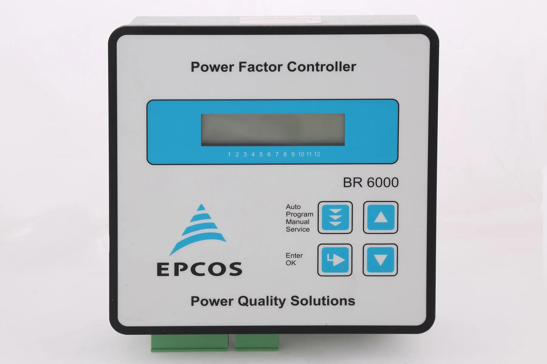
Power Factor Controller

Thyristor Regulator 6 and 12 Steps

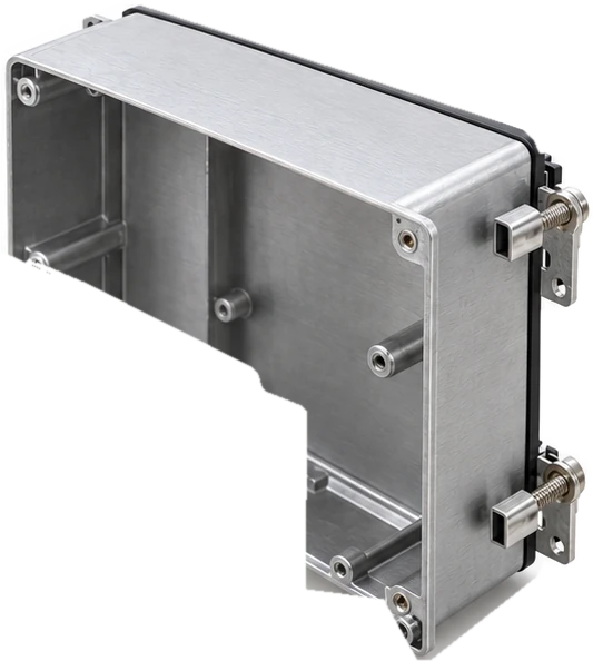
نمای انفجاری

What it is made of

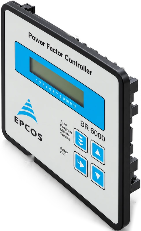
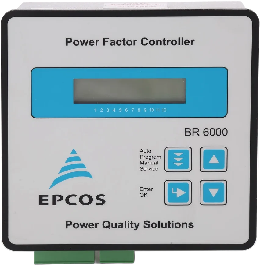
Real product photo
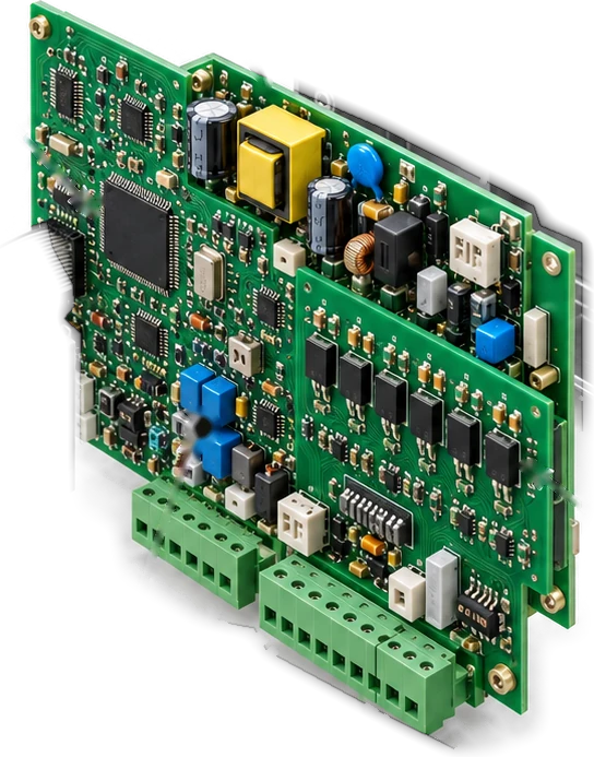
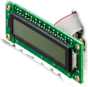
Illustrative exploded view; not to scale. Catalog dimensions and identity limitations are listed separately. Internal geometry and OEM subcomponent part numbers are unverified.

The numbers identify the parts in this drawing. They are not manufacturer part numbers.

فایل سازنده

Maker's file and catalogue

Catalogue code
B44066R6106E230Catalogue reference; the exact stocked part number is not confirmed
Model in the photograph
EPCOS BR 6000 (T6/T12 suffix not visible)

Maker's file (datasheet)

Film capacitors – Power Factor Correction / Power Factor Controller

Open the PDF

This is this product's own datasheet.

Maker
EPCOS AG
Revision
August 2015, Version: 2, Preliminary data
Covers
BR6000-T V6.0 · B44066R6106E230
This product's row
B44066R6106E230 · page 3
PDF
5 pages · thyristor-regulator-6-12-steps.pdf

In the catalogue

Catalogue dimensions

  • W 144 × H 144 × D 55 mmapplies to BR6000-T6 / B44066R6106E230Maker's file (datasheet) · page 3For another variant in the same document; not confirmed for this unit.
Review notes
  • Linked BR6000-T6 sheet has six transistor step outputs. Image uses solid-state output section, not mechanical step relay bank. Website title also mentions 12 steps; exact supplied variant needs verification.
  • Linked document specifies six transistor step outputs, whereas the listing mentions 6/12 steps. Artwork is a generic transistor-output family illustration; do not infer fitted output count from a generic front panel.

مشخصات فنی

Specifications

Series / type
BR6000-T V6.0
Ordering code
B44066R6106E230
Power Factor Controller · Film capacitors – Power Factor Correction · BR6000-T V6.0
Features
Display- Large and multifunctional LCD (2 x 16 characters) - Graphic and alphanumeric - LCD illumination
System parameters displayed- System voltage (V AC) - Reactive power (kvar) - Active power (kW) - Frequency - Apparent power (kVA) - Apparent current (A) - Temperature (°C / °F ) - Real-time cos - Target cos - Switchover cos-/tan-
Alarm output- Insufficient compensation - Overcompensation - Undercurrent - Overcurrent - Overtemperature - Threshold value programmable - Internal error storage nd - 2 signal relay random - Triggering time programmable
Recall recorded values- Maximum voltage, (Vmax) - Maximum reactive power, Q (kvar) - Maximum active power, P (kW) - Maximum apparent power, S (kVA) - Maximum temperature (°C)
Dynamic PFC- Direct triggering of thyristor modules series TSM
Technical data
Weight1 kg
CasePanel-mounted instrument, 144 x 144 x 55 mm (cut out 138 x 138 mm)
Ambient conditions
Over-voltage classIII
Pollution degree2
Operating temperature-20 ... +60 °C
Storage temperature-20 ... +75 °C
Sensitivity to inference (industrial areas)EN55082-2.1995
Spurious radiation (residential areas)EN55011 10.1997
Safety guidelinesIEC61010-1:2001, EN61010-1:2001
Mounting positionAny
Humidity class15 … 95% without dew
Front plateIP54 according to IEC60529
Rear sideIP20 according to IEC60529
Supply voltage110 … 230 V AC, 50 and 60 Hz power lines
Target cos0.3 inductive to 0.3 capacitive adjustable
Switching and discharge time range20 … 1000 ms
Number of control series20 series preset + control series editor for free programming
Control modes- Series switching (LIFO), - circular switching (FIFO), - self-optimized intelligent control mode
Measurement voltage range30 ... 525 V AC (L-N) or (L-L)
Fundamental frequency50 and 60 Hz
Measurement current (CT)x/5 and x/1 Ampere possible
Minimum operating current40 mA / 10 mA
Maximum current5.3 (sinusodial) < 15 ms
Number of outputs6
Switching voltage/power10 … 24 V DC
Alarm relayPotential-free contact (max. 250 V, 6 A)
From the manufacturer's datasheet

Features

  • (2 x 16 characters)
  • Graphic and alphanumeric
  • LCD illumination
  • Reactive power (kvar)
  • Active power (kW)
  • Frequency
  • Apparent power (kVA)
  • Apparent current (A)
  • Temperature (°C / °F )
  • Real-time cos
  • Target cos
  • Switchover cos-/tan-

نقشه‌ها

The maker's drawings

Power feedLoad sidesupply-voltageVbmeas.voltageVmmeas.currentIm (5A/1A)1. capacitorbranchL1 (R)L2 (S)L3 (T)NPEklT2AT2A(L)( N)(L3)L1(L2)NklVbVmImpower factorcontroller BR6000-T06abalarm relayP1P2123456transistor-output 1-6E.g. +24V-TSM-LC+-Connection diagramBR6000-T06EPCOS BR6000-T datasheet, p. 4
Connection planBR6000-T V6.0 (B44066R6106E230) — Connection plan, controller BR6000-T06Redrawn from the manufacturer's own file, page 4
14414455cut out 138 x 138Stated dimensions, mmBR6000-TEPCOS BR6000-T datasheet, p. 3
Outline, from stated dimensionsPanel-mounted instrument, 144 x 144 x 55 mm (cut out 138 x 138 mm)The maker prints no drawing of this device; this outline is drawn only from the dimensions its file states in text, page 3

Saba Khazen, Your Partner in Industry

Request a quoteTell us the rating and the quantity